When the model is solved, there are several groups of results specifically
for the
Access the
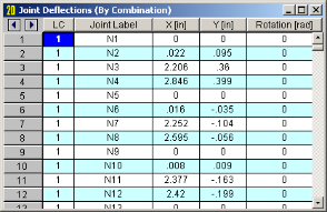
These are the deflections, or displacements, for every
For enveloped results the maximum and minimum value for each displacement is listed. The load combination producing the maximum or minimum is also listed, in the "lc" column. To include a particular Load Combination in the envelope analysis, open the Load Combinations Spreadsheet and check the box in the Solve column.
The moving load results are enveloped and will display the Load Combinations with maximum and minimum values shown for each section location, for each active member. The governing load combination and step location is shown for each result value under the "LC" column. The first number is the load combination, the second is the step number: (load combination - step number). See Moving Loads to learn more.
Note
Access the
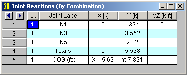
The Point Reactions are grouped into two tabs, you can view the results by load combination or by envelope. These are the reactive forces applied to the structure at its
points of support. A positive reaction is applied in the direction
Wall Panel Reactions represent the total reactions for the wall about the bottom center of the wall. This location does not change even if the center of the wall is within an opening, or if the edge of the wall is restrained as well as the base.
The last line provides the center of gravity (COG) for the applied loads. This "COG" is based on the load components acting in the VERTICAL direction. If there are no vertical loads in the combination a "COG" will not be calculated.
For enveloped results the maximum and minimum reaction value is listed. The load combination producing the maximum or minimum is also listed, in the "LC" column.
The moving results loads are enveloped and will display the Load Combinations with maximum and minimum values shown for each section location, for each active member. The governing load combination and step location is shown for each result value under the "LC" column. The first number is the load combination, the second is the step number: (load combination - step number). See Moving Loads to learn more.
Note